Building a Camera Slider Part 1
· 638 words · 3 minutes read
Last November I created my first timelapse which was all right, nothing to spectacular about it, however one tool that I’ve wanted to add to my arsenal for a while was a camera slider for taking time lapses. What a camera slider does is it moves the camera over the time of your timelapse to adjust the perspective, some more advanced ones even turn the camera so it’s pointed at the same point while moving. These can be mimicked in post processing, like I did with my previous timelapse but they aren’t quite the same because of the lack of perspective shift. With recently joining Seattle Makers, I thought it was a good oportunity to learn about 3d printing, laser cutting, as well as electronics while creating something that I’ve wanted for a while but can’t justify buying.
Over the next series of posts I’m going to walk you thru the steps of creating my design as well as show off some inspirations, and some failures I made along the way, so lets get into it.
The Design Itself
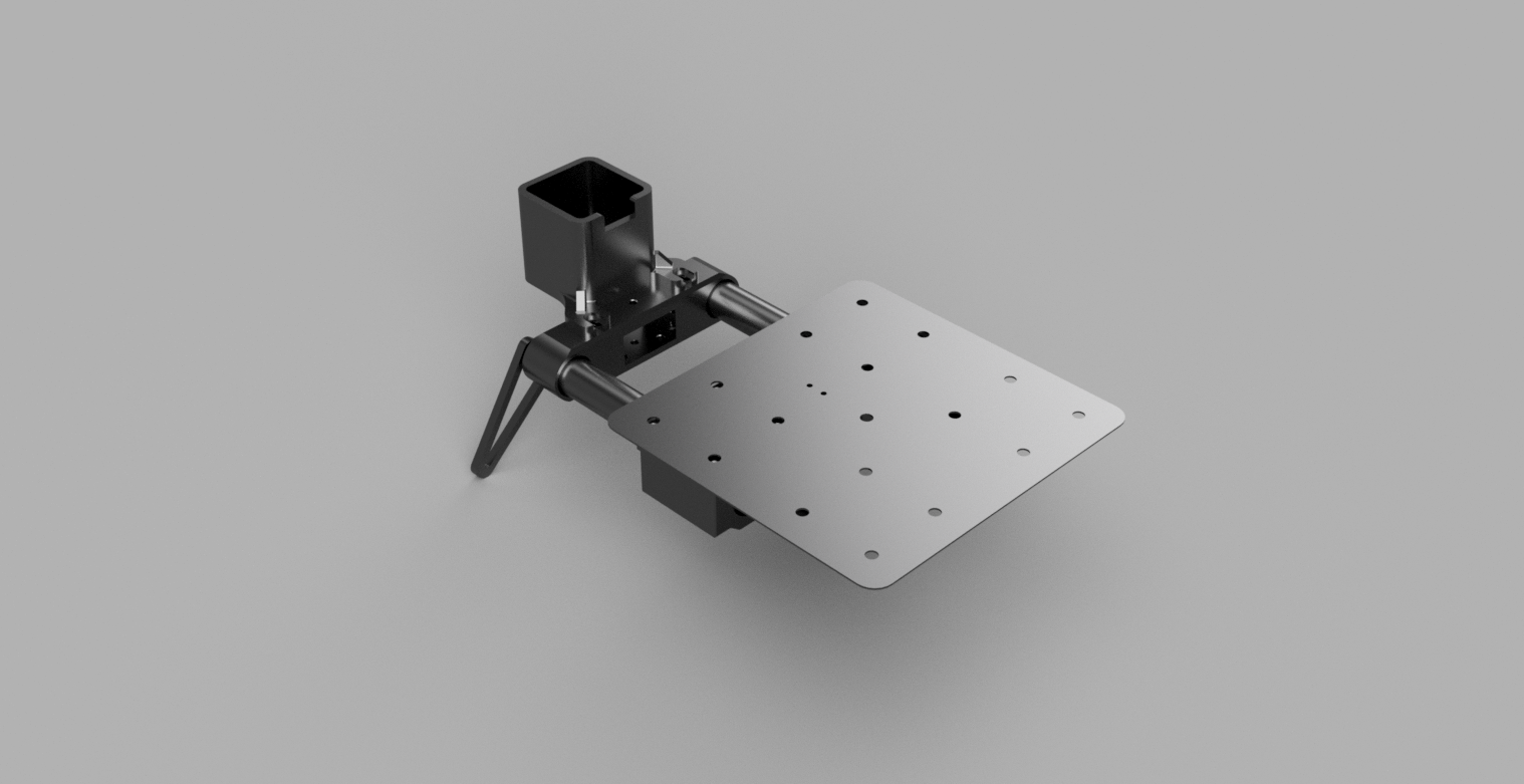
I started off by researching camera slider designed on Thingverse and found a few great ones, however because I wanted to try to create my own mostly from scratch I didn’t chose to use any of them directly but draw inspiration from them instead. The one that stood out the most was this one by swanglei. Overall it’s a really solid design by the looks of it and is hard to improve on, but that’s my goal. Overall our designs are somewhat similar because of my inspiration but I tried to simplify it a bit on the slider bits and make it more complex on the electronics which will be shown off in a future post (I don’t even have them in hand yet). My solution was to have a similarly shaped end pieces, and use steel rods instead of carbon fiber, I realize this makes it a-lot heavier, but I wanted to try to use linear bearings instead of the bearings and wheels running along the side. My feet are also simpler without having the adjustable pieces that using a screw, they are simply going to be laser cut. Also for the piece that the tripod and camera attaches to I plan to laser cut that as it takes way less time than 3d printing. For my motor I did chose to reuse swanglei’s motor mount, belt attachment, and wheel which are part of his electric driver upgrade located here. Those parts are relatively generic and I didn’t want to go out of my way to reinvent everything. Once that was all done I got to designing in Fusion 360 and came up with the following design:
Ⓒ 2018 Sean Smith
In the render I kept it simplistic, I only included 1 of the 4 legs, 2 of the 4 bearings, not including any of the actual electronics or the g2 beld that will run down the middle, and of course the shafts are much shorter than the ones I plan to use and are only there for reference. Overall I think most people will get an idea of the design from this render.
Why I think this is better (at the expense of weight which for some might be a no go) is because the linear bearings should give a much smoother motion to the camera. I also plan to code it up so that the electronics driving the motor knows when the camera is taking a picture and will not move. The reason for this should be obvious but in order to have a nice sharp image the camera shouldn’t be moving while taking a picture.
In my next post later this week I will be showing off my biggest fail (so far) of this project.